
DeFelsko manufactures hand-held, non-destructive ultrasonic coating thickness gages that are ideal for measuring the dry film thickness of paint applied to gypsum board (drywall / sheet rock / wallboard). This article will cover several measuring applications and challenges when measuring paint thickness on drywall. It will also cover the benefits of using a PosiTector 200 Ultrasonic Paint Thickness Gauge.
If you need to measure paint or coating thickness (DFT) on steel, aluminum, or other metals—see our selection of coating thickness gauges, articles, or videos for more information.
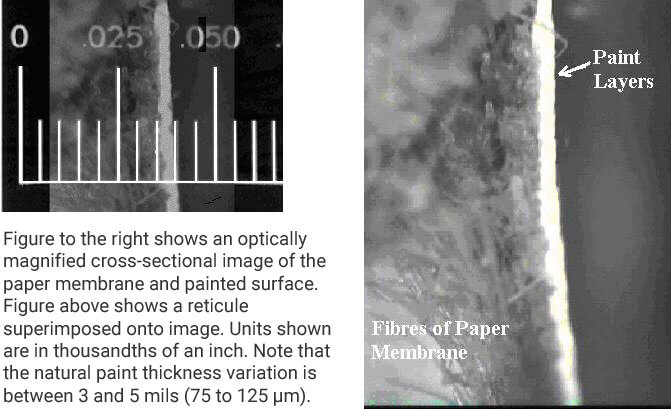
Drywall is typically painted with 3 layers (one primer and two paint layers). Traditionally a destructive test method is used to determine paint thickness. Today, the primary purpose of ultrasonic paint thickness testing is to non-destructively measure the TOTAL thickness of the paint system, typically in the range of 3 to 5 mils (75 –125 μm). Other challenges include a tendency for primer to absorb into the paper membrane of drywall, the effects of paint surface roughness or texturing, the impact of measuring over joint compound, and the potential need to measure individual paint or primer layers.
Two models are ideal for drywall.
View all of the PosiTector 200 features.
For those familiar with magnetic coating thickness gages, using ultrasonic coating thickness gages is easy and intuitive. The measurement method is simple and non-destructive. The displayed result is the total thickness of the coating system (primer + paint layers).
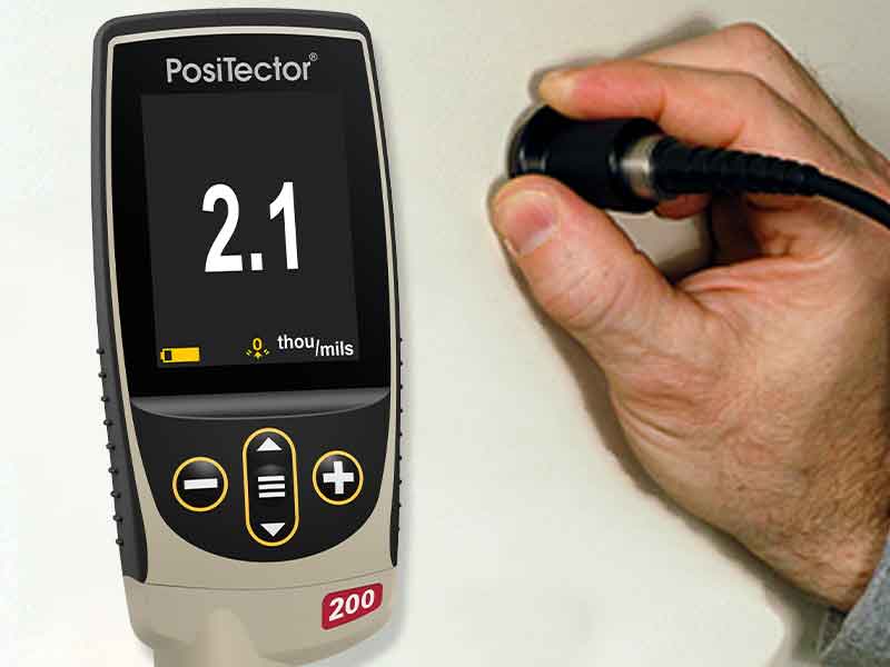
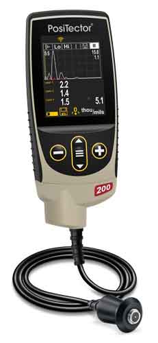
The PosiTector 200 B1 is ready to measure most drywall coating applications right-out-of-the-box. It has a measuring range of 13 to 1000 microns (0.5 to 40 mils) and is ideal for measuring the total thickness of the paint system. This basic version of the instrument requires no calibration adjustment for most applications, is mils/microns switchable and has a large, thick impact resistant color touchscreen display.
Drywall presents two distinct substrate surfaces to be coated: the face paper of the wallboard over the untreated area of the wallboard, and the taping compound over the seams, corners, and fasteners, (screws or nails). The PosiTector 200 B1 measures both without any special adjustments.
Some walls have coating systems that have been applied over many years in a number of layers. The DeFelsko PosiTector 200 B is the ideal solution when applicators only need to know the final, total thickness of the coating system. Since the primer coat is thin and mostly absorbed into the substrate material, it has minimal impact on the measured total thickness.
Some painted wall surfaces have a slight surface texture resulting from the application roller (see Fig.3).
On textured or rough surfaces the PosiTector 200 typically identifies the paint thickness from the top of the coating peaks down to the substrate. This is represented by distance #1 in Fig.4. Couplant fills the voids between the probe and the coating to assist the ultrasonic pulse enter the coating.
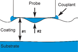
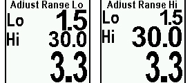
Sometimes this surface roughness can cause the gage to display low thickness values (distance #2). This happens because echoes from the couplant/coating interface are stronger than the coating/substrate interface. The PosiTector 200 has a unique user-adjustable SET RANGE feature (see Fig.5) to ignore roughness echoes.
Alternatively, see our article on the PosiTector 200’s Max Thick Mode for measuring total coating thickness on plastics, concrete, wood & more.
The PosiTector 200 B Advanced model provides additional information on surface texturing as described below.
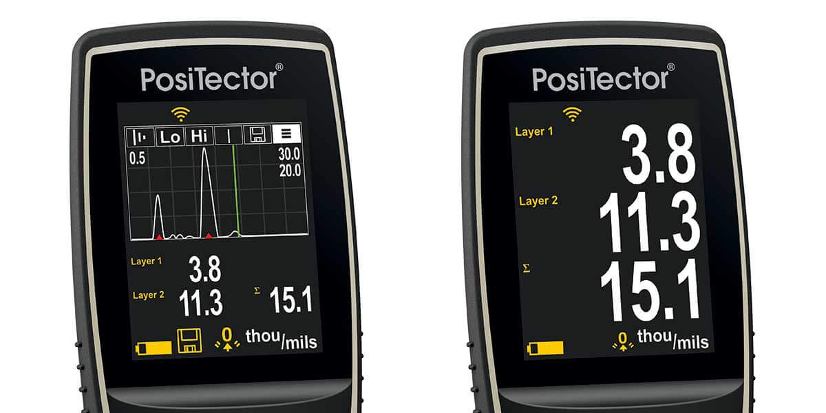
The advanced model, called the PosiTector 200 B3, is capable of measuring BOTH the total coating system thickness AND up to 3 individual layer thicknesses in a multi-layer system. It also features a graphic readout for detailed analysis of the coating system.
The gage’s large touchscreen display is capable of showing both numerical and graphical representations of the measurement. The graphical display can be set to appear on the right hand side of the screen. It shows a graphical representation of the ultrasonic pulse as it passes through the coating system.
Some painted wall surfaces have a slight surface texture resulting from the application roller (see Fig.3).
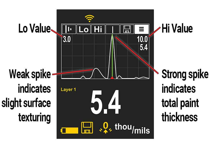
In the Screen Capture (Fig.7) the graphical display clearly identifies the total paint thickness by showing the strongest return echo from the ultrasonic pulse. The instrument’s graphical display may provide additional information. In this example it indicates the amount of surface texturing.
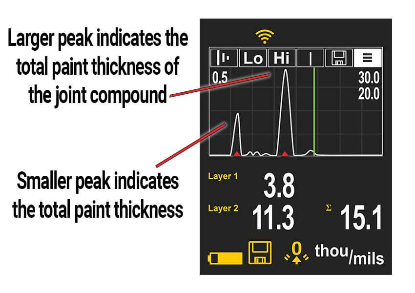
When taking total thickness measurements, periodic high readings will be displayed when the gage encounters joint compound covering the drywall seams. The resulting measurement would include the thickness of the joint compound in its total thickness calculation. This is due to a greater density differential between the drywall and joint compound, as compared to the joint compound and primer. By changing to a 2-layer application using the gage menu, the gage will individually identify the total paint thickness and the joint compound thickness as shown in Fig.8.
The multi-layer measurement capability of the PosiTector 200 B3 also has the potential to identify individual paint layer thickness, however, this would be application specific since the gauge is limited by the differences in acoustic velocity between the primer and paint layers. At a minimum, layers could be individually measured as each paint layer is applied, allowing the user to calculate the thickness of the most recently applied layer.
Ultrasonic measurement of coating thickness works by sending an ultrasonic vibration into a coating using a probe with the assistance of a couplant applied to the surface. A 4 oz bottle of a common water-based glycol gel is included with every instrument. Alternatively, a drop of water can serve as couplant on smooth, horizontal surfaces.
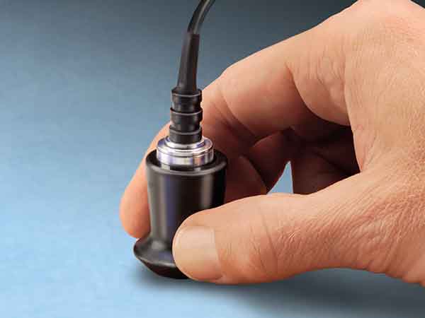
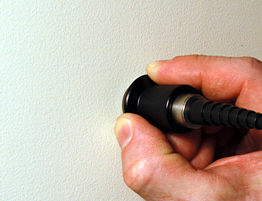
After a drop of couplant has been applied to the surface of the coated part, the probe is placed flat on the surface. Pressing down initiates a measurement (see Fig.9). Lifting the probe when a double beep is heard holds the last measurement on the digital display. A second reading may be taken at the same spot by continuing to hold the probe down on the surface. When finished, wipe the probe and the surface clean with a tissue or soft cloth.
The accuracy of any ultrasonic measurement directly corresponds to the sound velocity of the finish being measured. Because ultrasonic instruments measure the transit time of an ultrasonic pulse, they must be calibrated for the “speed of sound” of that particular material.
From a practical standpoint, sound velocity values do not vary greatly among the coating materials used in the wood industry. Therefore, ultrasonic coating thickness gages usually require no adjustment to factory calibration settings.
Refer to the PosiTector 200 instruction manual for information on making a user-adjustment.
The PosiTector 200 B Advances' screen can be used to display a graphical representation of the ultrasonic pulse as it passes through the coating system. This powerful tool enables the user to better understand what the gage “sees” below the surface of the coating.
As the probe is depressed and the ultrasonic pulse travels through the coating system, the pulse encounters changes in density at the interfaces between coating layers and between the coating and the substrate.
A “peak” depicts these interfaces. The greater the change in density, the higher the peak. The more gradual the change in density, the greater the width of the peak. For example, two coatings layers made of essentially the same material and "blended" would result in a low, wide peak. Two materials of very different density and a well-defined interface would result in a high, narrow peak.
The PosiTector 200 B3 chooses the highest of peaks when trying to determine coating layer thickness. For example, if the number of layers is set to 3, the 3 highest peaks between the Lo & Hi SET RANGE are selected as the interfaces between these layers. The peaks that the Gage selected are indicated by red triangle arrows (see Fig.11).
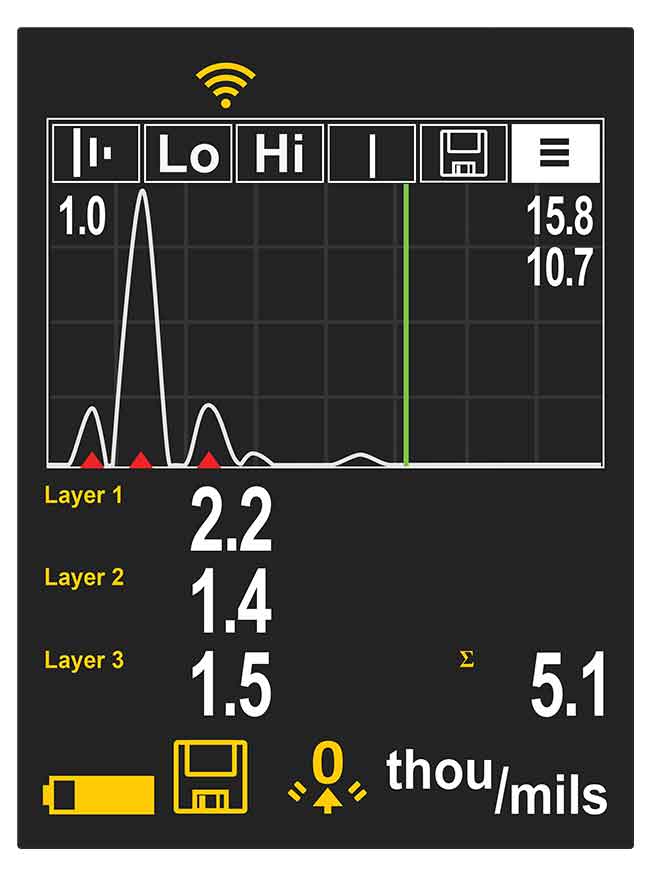
In Fig. 11, the top (Lo = 1.0 mils) and bottom (Hi = 15.8 mils) Range values are displayed as two horizontal lines at the top and bottom of the graphics area. Lo (the minimum limit) is at the top. Hi (the maximum limit), is at the bottom. Echoes or peaks (thickness values) outside these ranges are ignored. Range values are set and modified using the SET RANGE menu option.
This Graphics display can be manipulated with the SET RANGE menu option. In addition to being able to adjust the range values, a Cursor can be positioned anywhere between the two range values to investigate other peaks.
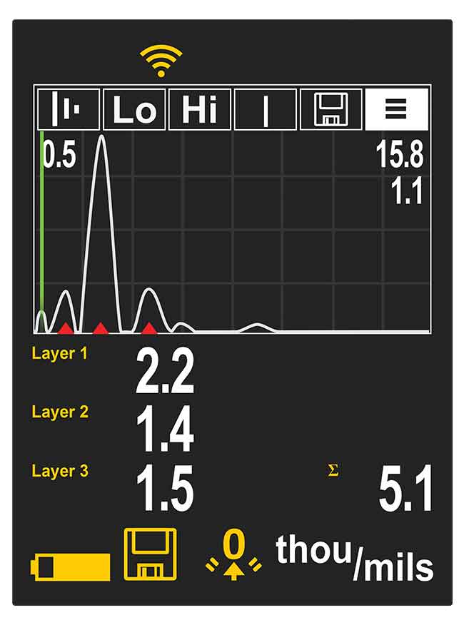
A cursor is used when there are more than 3 layers. In this example, the instrument combines the top two layers into a 2.2 mil result. The cursor determines the top layer to be 1.1 mils. The second layer is therefore 1.1 mils (2.2 - 1.1).
Conventional magnetic and eddy-current gages only work on metals. Measuring on drywall required other measuring techniques, including:
These techniques are time-consuming, difficult to perform, and are subject to operator interpretation and other measurement errors. Applicators find destructive methods impractical.
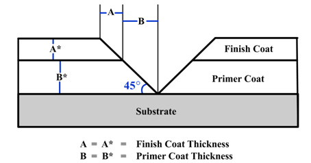
A typical destructive technique requires cutting the coated part in a cross section and measuring the film thickness by microscopically viewing the cut. Another cross sectioning technique uses a scaled microscope to view a geometric incision through the dry-film coating. To do this, a special cutting tool makes a small, precise V-groove through the coating and into the substrate (see Fig.12). Gages are available that come complete with cutting tips and illuminated scaled magnifiers. A detailed description of this test method is provided in ASTM D4138-07a, “Standard Practice for Measurement of Dry Film Thickness of Protective Coating Systems by Destructive, Cross-Sectioning Means”.
Although this method's principles are easy to understand, opportunities abound for introducing errors. It takes skill to prepare the sample and interpret the results. Also, adjusting the measurement reticule to a jagged or indistinct interface can generate inaccuracy, particularly between different operators. This method is used when inexpensive, nondestructive methods aren't possible, or as a means of confirming nondestructive test results.
With the arrival of ultrasonic instruments, many coaters have switched to non-destructive inspection.
Gypsum "boards" are formed by sandwiching a core of wet plaster between two sheets of heavy paper. When the core sets and is dried, the sandwich becomes a strong, rigid, fire-resistant building material. Fire-resistant because in its natural state, gypsum contains water, and when exposed to heat or flame, this water is released as steam, retarding heat transfer. Manufactured in large quantities on continuous machines, gypsum wallboard and lath, prefinished wallboard, and gypsum sheathing for use under exterior finishes are among the most important materials used in housing. ASTM C1597M-04 and ASTM C1396C/1396M-17 describe specifications for gypsum wallboard.
Most drywall primers are water-based, polyvinyl acetate (PVA) formulations. They are relatively inexpensive and will not lift the paper of the drywall. Their purpose is to seal the surface of the drywall and joint compound. This helps ensure that the finish coat will have a uniform appearance.
Manufacturers and applicators alike have long believed that there is no simple and reliable means for non-destructively measuring coatings on plastic substrates. Their common solution was to place metal (steel or aluminum) coupons next to the part and then measure the thickness applied to the coupon with either a mechanical or electronic (magnetic or eddy current) gage. This labor intensive solution is based on the assumption that a flat coupon placed in the general coating area receives the same paint profile as the plastic part in question. An ultrasonic solution enables the user to measure the total coating thickness of the actual part. Dependent on the ultrasonic gage utilized and the coating application process, an added advantage is the ability to identify multiple distinct layers.
Ultrasonic coating thickness measurement is now an accepted and reliable testing routine used in wood industries. The standard test method is described in ASTM D6132. “Standard Test Method for Nondestructive Measurement of Dry Film Thickness of Applied Organic Coatings Using an Ultrasonic Gage” (2022, ASTM). To verify gage calibration, coated thickness standards are available with certification traceable to national standards organizations.
Quick, non-destructive thickness measurements can now be taken on materials that previously required destructive testing or lab analysis. This technology improves consistency and throughput in the finishing room. Potential cost reductions include:
Today, these instruments are simple to operate, affordable and reliable.
Couplant is required to propagate ultrasound into the coating. Water is a good couplant for smooth coatings. Use the supplied glycol gel for rougher coatings. While it is unlikely that the couplant will damage the finish or leave a stain on the surface, we suggest testing the surface by using the couplant on a sample. If testing indicates that staining has occurred, a small amount of water can be used instead of couplant. Consult the Safety Data Sheet available on our website and your coating supplier if you suspect the couplant may damage the coating. Other liquids such as liquid soap may also be used.
The PosiTector 200 Standard models can record 1,000 measurements. PosiTector 200 Advanced models can store 250,000 measurements in up to 1,000 batches for on-screen statistical purposes, for printing to an optional Bluetooth Wireless Printer, or for downloading to a personal computer using the included USB Cable and one of the PosiSoft Solutions.

.png)


