
Measuring physical parameters such as coating thickness, surface profile, and dew point is a common task for inspectors and applicators. However, those measurements are only as accurate as the instrument that performs them. Even high-quality electronic instruments can yield incorrect measurements if three key steps are not followed: Calibration, Verification, and Adjustment. In this paper, these often-misunderstood steps are explained as defined by ASTM D70911, ISO 28082 and SSPC-PA 23. The importance of a 'long form' Calibration Certificate, who can perform a calibration, and the applications that may require field adjustments will also be discussed.
The word "calibration" has different meanings depending on the industry or setting in which it is used. There's a good chance someone you know misunderstands the terms Calibration and Calibration Interval as they relate to the coating inspection industry. They would be surprised to learn that, not only can they not calibrate their gage themselves, but there is usually no fixed recalibration interval either.
For an indication of how challenging it is to define calibration terms, one needs to look no further than the myriad of definitions available from major organizations. It's not surprising that explanations differ given the challenges of defining a word used in many industries for many types of instruments.
A simpler approach is to explain calibration terms as they pertain to a specific industry segment, in this case, the protective coatings industry. Here ISO, ASTM, SSPC and others generally agree.
Calibration in the Coatings Inspection Industry
ASTM D7091 describes the use of magnetic eddy current gages for dry film thickness and is typical of many standards. It defines calibration as the:
"...high-level, controlled and documented process of obtaining measurements on traceable calibration standards over the full operating range of the gage, then making the necessary gage adjustments (as required) to correct any out-of-tolerance conditions. Calibration of coating thickness gages is performed by the equipment manufacturer, their authorized agent, or by an accredited calibration laboratory in a controlled environment using a documented process. The outcome of the calibration is to restore/realign the gage to meet/exceed the manufacturer's stated accuracy."
Within that definition there are a few terms worthy of additional discussion:
"Traceable Calibration Standard": Fundamentally, the purpose of calibration is to ensure an instrument reads within tolerance to a standard of a known value. Quantifying these known values (weight, distance, etc.) is the responsibility of an organization called the International Bureau of Weights and Measures (BIPM).
The BIPM works with National Metrological Institutes such as the NIST (USA), NPL (UK), and PTB (Germany), who maintain Standard Reference Materials (SRMs) for standard measures such as length, weight, and time. These SRMs are highly accurate artifacts that are used as calibration standards for the most precise measurement equipment.
Because it's not affordable, efficient or even possible for everybody to calibrate against an SRM, the SRMs are used to calibrate primary calibration standards; secondary standards are used to calibrate working standards; and working standards are used to calibrate process instruments. Through this 'chain' of standards, instruments are ultimately traceable directly to an SRM artifact without needing to ever measure that artifact.
Since an instrument or standard is always less accurate than the standard that calibrates it, an increase in uncertainty occurs as one moves further down the chain of standards.
A Test Uncertainty Ratio (TUR) of 4:1 is generally accepted in industry, meaning that the tolerance of an instrument is four times greater than the uncertainty of the standard that it was measured against. For example, when using a TUR of 4:1, a coating thickness gage that was calibrated against standards with an uncertainty of ± 0.05 mils would have a stated tolerance or accuracy of ± 0.2 mils.
Under a Mutual Recognition Agreement that was signed between the major National Metrological Institutes, all participating institutes recognize the validity of each other's calibration and measurement certificates.
"Accredited Calibration Laboratory": ASTM D7091 limits the parties who can perform a calibration to "the equipment manufacturer, their authorized agent, or... an accredited calibration laboratory". While the first two categories are self-evident, the concept of an 'accredited calibration laboratory' is less clear. ISO/IEC 17025 sets out the requirements for accreditation and Laboratories can receive such accreditation through an accreditation body that is a signatory to the International Laboratory Accreditation Cooperation (ILAC) agreement.
However, a laboratory's ISO 17025 accreditation only applies to specific calibration activities. A laboratory's scope of accreditation lists the activities that a laboratory is accredited to perform, in addition to the measurement uncertainty that the laboratory is capable of calibrating to. If using a third-party calibration laboratory, it is crucial to ensure not only that it is accredited, but also that its accredited scope includes the instruments that you are seeking to have calibrated. While a great number of ISO 17025 accredited labs exist, few are accredited to calibrate coating inspection equipment.
When an instrument is calibrated, a document called a Certificate of Calibration is issued (Figure 1). This document records actual measurement results and all information relevant to a successful instrument calibration including traceability to a national standard. Job specifications often require proof of a recent calibration.
Many manufacturers of test equipment do not supply Certificates of Calibration. Instead, they may supply 'certificates of conformance', 'certificates of compliance', 'certificates of accuracy' or 'certificates'. These are little more than a manufacturer's statement of accuracy, requiring the user to trust that the instrument will measure accurately. Such 'certificates' do not meet the definition of calibration under ASTM D7091 and other standards, and are also typically inadequate for in-house, contract, or regulatory requirements.
While the form and content of calibration certificates varies, a proper certificate must contain specific minimum information that assures compliance with ISO/IEC 17025 requirements. Figure 1 shows an example of a calibration certificate, with each of the important attributes highlighted.
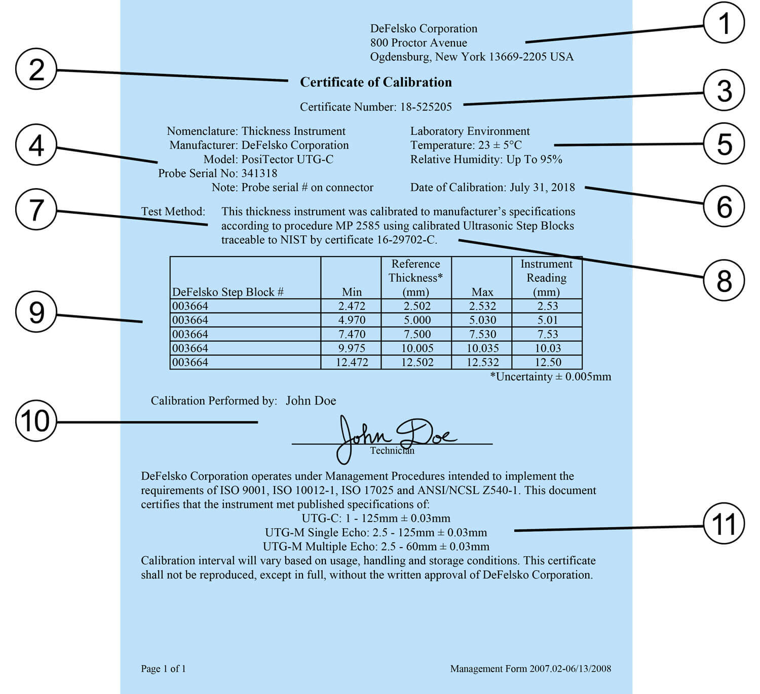
If the certificate issued by the calibration laboratory or instrument manufacturer doesn't include these important attributes, it likely isn't a Certificate of Calibration as defined by most standards and contracts.
Recalibration (or recertification) is periodically required throughout the life cycle of an instrument since the accuracy of most measuring devices degrades with use. A Calibration Interval is the established period between recalibrations of an instrument. As per the requirements of ISO 17025, most manufacturers do not include calibration intervals as part of Calibration Certificates. Why? Because they don't know how frequently the gage is used, what environment it is used in, and how well it is looked after4.
If you don't have experience with an instrument, one year is a good starting interval between calibrations. This can be adjusted with experience, and regular verification (see below). Customers with new instruments can utilize the date the instrument was placed into service (or the purchase date) as the beginning of their first calibration interval. The negligible effect of shelf life minimizes the importance of the actual calibration certificate date.
A calibration certificate does not guarantee accuracy will be maintained throughout the calibration interval. Numerous factors can detrimentally affect gage operation, such as accidental damage or accumulation of debris. To guard against measuring with an inaccurate gage, most standards require accuracy and operation be verified before each use, typically at the beginning of every work shift. It should be rechecked after large numbers of measurements have been obtained, if the gage is dropped, or if it is suspected of giving erroneous results. Often contracting parties reach an initial agreement of the details and frequency intervals of verifying gage accuracy.
What do you do at these intervals? That depends upon the quality system you have in place. Some owners simply measure a sample part when their gage is new and record the result. This sample is then saved and used to regularly check operation and accuracy of the gage.
The best and most universally accepted method for checking accuracy, however, is to measure Calibration Standards in a controlled environment using a documented procedure. ASTM D7091 contains language typical of many standards:
"7.3 Verification of Accuracy—Before use, each instrument's calibration accuracy shall be verified by the user in accordance with the instructions of the manufacturer, employing suitable coating thickness standards and, if necessary, any deficiencies found shall be corrected. The gage should be verified for accuracy in the intended range of use."
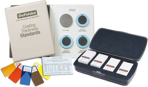
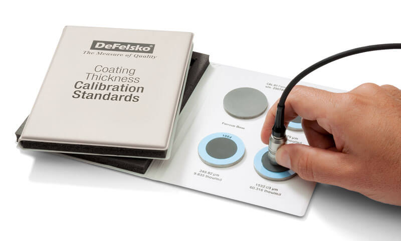
Calibration Standards take many forms, depending on the instrument being verified. They must be traceable to a National Metrological institute and have a measurement value within the range of the gage - ideally, near the expected range of measurement. The process of measuring them is described in a document called a Calibration Procedure which some manufacturers publish or provide upon request.
For coating thickness gages, Coating Thickness Standards are available as either certified coated metal plates or plastic shims. Plates are usually more accurate and durable, but also costlier. Type 1 (mechanical) coating thickness gages cannot be verified using plastic shims.
The average of a series of readings should be within the combined tolerances of both the gage and the reference standard. To determine the combined tolerance, the tolerances of the gage and standard aren't simply added together, rather, the 'sum of squares' formula should be used. For example, if the reference standard's accuracy is ±2% and the instrument's accuracy is ±3%, the combined tolerance is ±3.6%, computed as:
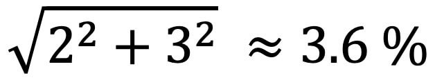
If the readings are outside the combined tolerance, there is a problem with the gage or reference standard. The problematic gage or reference standard should be identified, and all measurements made since the last accuracy check should be considered suspect.
For many inspection instruments, Calibration and Verification are sufficient to ensure the instrument is measuring properly. However, for coating thickness gages, a third step is often necessary: Adjustment. This is because coating thickness gages do not directly measure the thickness of the coating; instead, they measure the magnetic properties of the substrate. These properties weaken as the probe moves away from the substrate and are therefore related to coating thickness.
However, there are other factors that can affect the magnetic properties of the substrate. These include:
Coating thickness gages are usually factory calibrated to perform well on flat, smooth carbon steel. However, they can measure accurately on applications with varying surface roughness, geometry, composition, or mass if an adjustment is performed:
"3.1.2 adjustment—the physical act of aligning a gage's thickness readings to match those of a known thickness sample (removal of bias), in order to improve the accuracy of the gage on a specific surface."
It is important to note that any adjustment only accounts for the substrate roughness, geometry, composition and/or mass at the location the adjustment was performed. If any of these factors change across the part or job, further adjustment is often required. Some electronic instruments, such as PosiTector 6000 Advanced models, are able to save multiple calibration adjustments so that the user can choose the adjustment that best suits the application at hand.
It should also be noted that not all coating thickness gages are alike. Consult the manufacturer or the instrument's user manual for the best guidance on how to adjust your particular instrument. The following overview is a guide to adjusting one type of common coating thickness gages.
To determine if an instrument requires adjustment, check that the average of a series of readings on the uncoated substrate is within the gage tolerance at zero. If measuring out of tolerance, and adjustment to the gage is likely required. This is often as simple as offsetting all future measurements by the error encountered during the check measurement. Type II electronic gages like the PosiTector 6000, typically have a built-in 'zero adjustment' feature to make the process automatic. If subsequent measurements of the uncoated substrate read within tolerance at zero, the adjustment has been performed successfully. Type I mechanical pull-off gages such as the PosiTest have nonlinear scales, so the instrument itself shouldn't be adjusted. Instead, the user should take a base metal reading (BMR) and subtract that value from future coating thickness readings.
For nearly all applications, the instrument will measure within tolerance throughout its entire range after a zero adjustment has been successfully performed. This can be verified by placing a shim on the uncoated substrate and ensuring that the gage reading is within the combined tolerance of the shim and gage. In the rare circumstance where the gage reads within tolerance at zero but outside of tolerance on a shim, a further adjustment may be required. Consult the manufacturer of the product manual for further details.
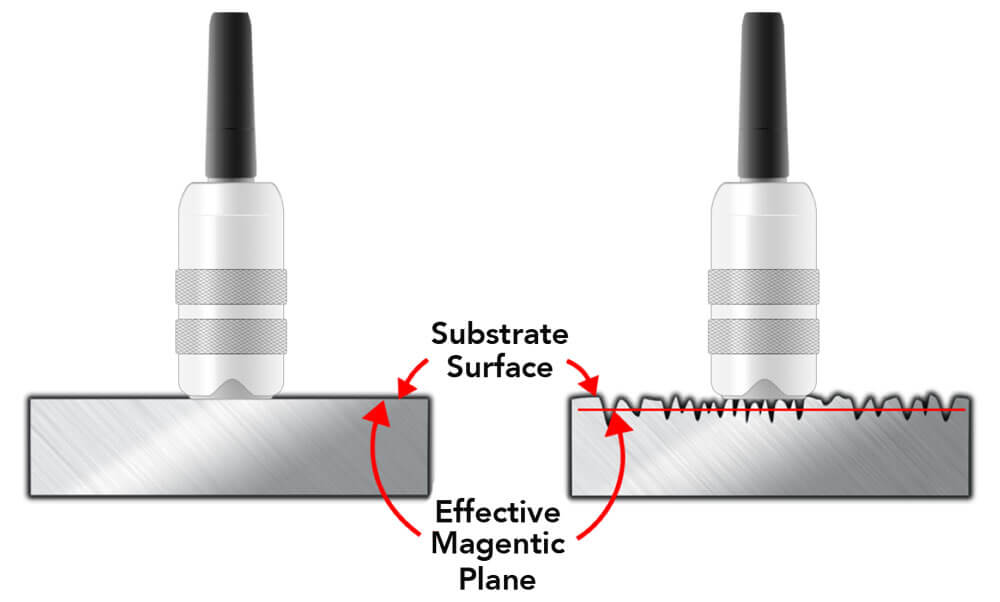
While a zero adjustment is often sufficient to account for the effects of geometry, composition, and mass, a zero adjustment shouldn't be performed on blasted or roughened surfaces. On those surfaces, coating thickness gages will measure to a point between the peaks and valleys of the roughness called the 'magnetic plane'. Since most standards and specifications indicate that only the coating thickness over the peaks of the surface profile be reported, and adjustment is needed.
The ensure a coating thickness gage will measure the thickness of the coating 'above the peaks' of the surface profile, the accepted procedure is to adjust to the known thickness of a shim placed over the uncoated substrate. The shim rests on the peaks of a surface profile, or other pattern, and is a substitute for the coating film that will eventually be applied. Type II electronic gages typically have a built-in '1-point adjustment' feature to make the process simple.
Since Type I mechanical pull-off gages typically use a large magnet to contact the surface instead of a small probe tip, they are less affected by surface roughness. The user can simply perform a zero adjustment by taking a base metal reading (BMR) on the uncoated, blasted substrate and subtract that value from future coating thickness readings.
1 ASTM D7091 "Standard Practice for Nondestructive Measurement of Dry Film thickness of Nonmagnetic Coatings Applied to Ferrous Metals and Nonmagnetic, Nonconductive Coatings Applies to Non-Ferrous Metal" (ASTM International, 100 Barr Harbor Drive, West Conshohocken, PA 19428), www.astm.org
2 ISO 2808, Paints and Varnishes – Determination of film thickness. Available from American National Standards Institute (ANSI), 25 W. 43rd St., 4th Floor, New York, NY 10036, http://www.ansi.org
3 SSPC PA2, Procedure for Determining Conformance to Dry Coating Thickness Requirements. Available from Society for Protective Coatings (SSPC), 40 24th St., 6th Floor, Pittsburgh, PA 15222-4656, http://www.sspc.org
4 Looking After Your Coating Thickness Gage, David Beamish, PCE - Protective Coatings Europe, and JPCL Equipment Maintenance, April 2005

DAVID BEAMISH (1955 – 2019), former President of DeFelsko Corporation, a New York-based manufacturer of hand-held coating test instruments sold worldwide. He had a degree in Civil Engineering and more than 25 years of experience in the design, manufacture, and marketing of these testing instruments in a variety of international industries including industrial painting, quality inspection, and manufacturing. He conducted training seminars and was an active member of various organizations including NACE, SSPC, ASTM and ISO.

.png)


