
DeFelsko manufactures hand-held, non-destructive ultrasonic coating thickness gages that are ideal for non-destructively measuring the dry film thickness of coatings on plastic. Many industries now use this nondestructive technology in their quality programs.
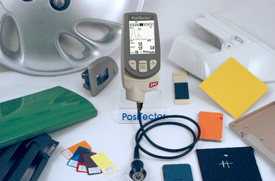
Two models are ideal for plastic substrates.
Measuring Applications:
Additional Notes:
Some plastic coating systems are applied in a number of layers to achieve their desired objective. Our PosiTector 200 B1 is the ideal solution when applicators only need to know the final, total thickness of the coating.
The PosiTector 200 B1 is ready to measure most plastic coating applications right-out-of-the-box. It has a measuring range of 13 to 1000 microns (0.5 to 40 mils) and is ideal for measuring total coating system thickness. It requires no calibration adjustment for most applications, is mils/microns switchable and has a large, thick impact resistant Lexan display.
For those familiar with magnetic coating thickness gages, using ultrasonic coating thickness gages is easy and intuitive. The measurement method is simple and non-destructive.
Coatings with rough surfaces challenge any measurement method, and ultrasonic testing is no exception. The PosiTector 200 is equipped to handle these situations.
At a microscopic level, thickness can vary (see Fig.2). Meaningful thickness measurements are best obtained by taking several measurements in the same general location and averaging the results.
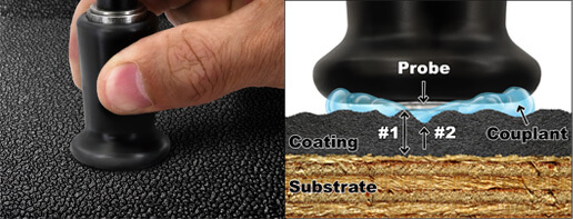
On rough surfaces the PosiTector 200 typically identifies the thickness from the top of the coating peaks down to the substrate. This is represented by distance #1 in the Fig.2. Couplant fills the voids between the probe and the coating to assist the ultrasonic pulse enter the coating.
Severe roughness can cause the gage to display low thickness values (distance #2). This happens because echoes from the couplant/coating interface are stronger than the coating/substrate interface. The PosiTector 200 has a unique user-adjustable SET RANGE feature to ignore roughness echoes.
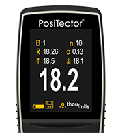
For these applications, the memory mode of the PosiTector 200 provides assistance. With memory turned ON, the PosiTector 200 calculates and displays the number of readings taken, the average of those readings, the standard deviation of those readings, and the highest and lowest readings (see Fig.3). The supplied couplant works better than water on rough surfaces.
The PosiTector 200 B3 is capable of measuring BOTH the total coating system thickness AND up to 3 individual layer thicknesses in a multi-layer system. It also features a graphic readout for detailed analysis of the coating system.
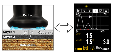
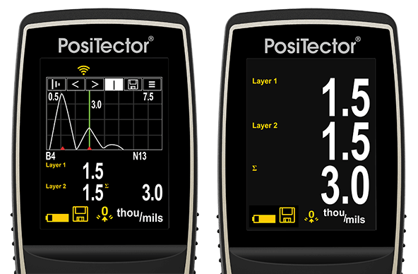
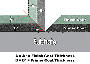
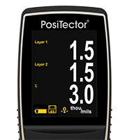
In the above example, layer 1 is 1.5 mils thick. Layer 2 is 1.5 mils thick. Total thickness is 3.0 mils. The graphical LCD displays two “peaks” representing two material interfaces. A two-step process adjusts the instrument for multi-layer applications.
A large number of plastic components are present both in car interiors and exteriors. Very often these plastic components have to be coated, for aesthetic and protection requirements.
Interior components like dashboards, door panels, airbag covers, steering wheels etc, are more challenging to measure for two reasons. First, many components are too small or too geometrically complex for the PosiTector 200’s probe to access properly. Second, some parts either have a very thin coating or a coating too rough for the gage to measure consistently. The gage performs best on a smooth, flat, hard surface with a coating thickness of at least 13 microns (0.5 mil).
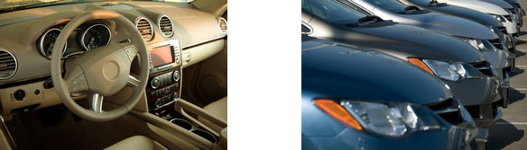
Exterior components like bumpers, mirror shells, side claddings, etc. can be measured provided the PosiTector 200’s probe can again access the surface to be measured. The gage can measure the total thickness of most applications, and can measure some individual layers in a multi-layer system.
Automotive coating systems are comprised of several coating layers. The basic PosiTector 200 B1 model is capable of measuring the total thickness of these coating systems.
The adhesion promoter and primer layers in automotive applications are typically too thin for the more advanced PosiTector 200 B3 model to measure individually. So the instrument combines their thicknesses with the base coat thickness to produce a total result. The top, clear coat layer is measured separately and individually.
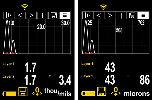
Figure 5 is typical of results from the PosiTector 200 B3 on exterior automotive plastic. The image on the left shows a measurement using imperial (mils) units. The right image is the equivalent measurement in metric (microns). Although the coating system is comprised of 4 layers, the instrument combines the thicknesses of the first 3 layers (adhesion promoter, primer, base coats) into one value of 1.7 mils (43 microns). The final top clear coat is measured individually as 1.7 mils (43 microns). The total coating system thickness is 3.4 mils (86 microns).
This result is useful when the final clear coat thickness is the important layer to determine. Auto detailers use this feature to view the remaining amount of clear coat while polishing. Applicators use this feature to ensure consistent application thickness.
Ultrasonic probes discussed in this article have an 8 mm (0.3") diameter flat measurement surface that should fully contact the coated plastic for best measurement results. Measurements taken on curved surfaces may require averaging of multiple readings for meaningful results.
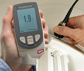
Ultrasonic measurement of coating thickness works by sending an ultrasonic vibration into a coating using a probe with the assistance of a couplant applied to the surface. A 4 oz bottle of a common water-based glycol gel is included with every instrument. Alternatively, a drop of water can serve as couplant on smooth, horizontal surfaces.
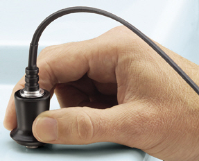
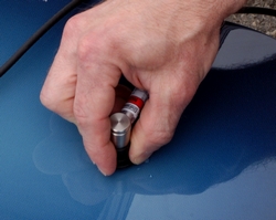
After a drop of couplant has been applied to the surface of the coated part, the probe is placed flat on the surface. Pressing down initiates a measurement (see Fig.6). Lifting the probe when a double beep is heard or when the green indicator light blinks holds the last measurement on the LCD. A second reading may be taken at the same spot by continuing to hold the probe down on the surface. When finished, wipe the probe and the surface clean with a tissue or soft cloth.
Measurement Accuracy
The accuracy of any ultrasonic measurement directly corresponds to the sound velocity of the finish being measured. Because ultrasonic instruments measure the transit time of an ultrasonic pulse, they must be calibrated for the “speed of sound” in that particular material.
From a practical standpoint, sound velocity values do not vary greatly among the coating materials used in the plastics industry. Therefore, ultrasonic coating thickness gages usually require no adjustment to factory calibration settings.
The right hand side of the PosiTector 200’s screen can be used to display a graphical representation of the ultrasonic pulse as it passes through the coating system. This powerful tool enables the user to better understand what the gage “sees” below the surface of the coating.
As the probe is depressed and the ultrasonic pulse travels through the coating system, the pulse encounters changes in density at the interfaces between coating layers and between the coating and the substrate.
A “peak” depicts these interfaces. The greater the change in density, the higher the peak. The more gradual the change in density, the greater the width of the peak. For example, two coatings layers made of essentially the same material and "blended" would result in a low, wide peak. Two materials of very different density and a well-defined interface would result in a high, narrow peak.
The PosiTector 200 B3 chooses the highest of peaks when trying to determine coating layer thickness. For example, if the number of layers is set to 3, the 3 highest peaks between the Lo & Hi Ranges are selected as the interfaces between these layers. The peaks that the Gage selected are indicated by red triangle arrows (see Fig.9).
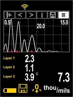
In Fig. 9, the top (Lo = 0.5 mils) and bottom (Hi = 15.0 mils) Range values are displayed as two horizontal lines at the top and bottom of the graphics area. Lo (the minimum limit) is at the top. Hi (the maximum limit) is at the bottom. Echoes or peaks (thickness values) outside these ranges are ignored. Range values are set and modified using the SET RANGE menu option.
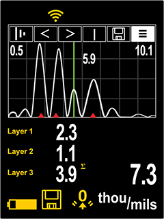
This Graphics display can be manipulated with the SET RANGE menu option. In addition to being able to adjust the range values, a Cursor can be positioned anywhere between the two range values to investigate other peaks.
Conventional magnetic and eddy-current gages only work on metals. So the plastics industry has relied on other measuring techniques including:
These techniques are time-consuming, difficult to perform, and are subject to operator interpretation and other measurement errors. Applicators find destructive methods impractical. To get a statistically representative sample, several wood products from a lot might need to be scrapped as part of the destructive testing process.
A typical destructive technique requires cutting the coated part in a cross section and measuring the film thickness by microscopically viewing the cut. Another cross sectioning technique uses a scaled microscope to view a geometric incision through the dry-film coating. To do this, a special cutting tool makes a small, precise V-groove through the coating and into the substrate (see Fig.11). Gages are available that come complete with cutting tips and illuminated scaled magnifiers. A detailed description of this test method is provided in ASTM D4138-07a, “Standard Practice for Measurement of Dry Film Thickness of Protective Coating Systems by Destructive, Cross-Sectioning Means”.
Although this method' s principles are easy to understand, opportunities abound for introducing errors. It takes skill to prepare the sample and interpret the results. Also, adjusting the measurement reticule to a jagged or indistinct interface can generate inaccuracy, particularly between different operators. This method is used when inexpensive, nondestructive methods aren't possible, or as a means of confirming nondestructive test results.
With the arrival of ultrasonic instruments, many coaters have switched to non-destructive inspection.
What is the Application?
The coating of plastics, particularly in the automotive industry involves the application of several coating layers to attain full aesthetic appearance and protective properties. Not only does exterior finish tend to be a strong reflection of the quality and durability of costly consumer products, but also coatings for plastic components need to address the challenges unique to plastic substrates including adhesion, flexibility, and temperature constraints.
Common plastic substrates (i.e. polyethylene, polypropylene, thermoplastic polyolefin, ABS, nylon, PVC) are nonporous, resistant to most solvents, and have low surface energy compared to other materials. This makes the plastic surface difficult to wet and provides the coatings little opportunity to adhere by penetrating or physically locking into surface irregularities. To counter these difficulties, adhesion promoters are used as paint additives or as primers to promote adhesion of coatings to their substrates. An adhesion promoter usually has an affinity for the substrate and the applied coating, enabling applied coatings to meet the intended performance requirements.
Automotive Coatings
In automotive coatings, the term adhesion promoter refers to the primer (typically chlorinated polyolefin or other modified polyolefin's), which facilitates adhesion of the subsequent paint layer to the plastic. Typically adhesion promoters are applied to achieve a dry film thickness of 0.3 – 0.5 mils (7.5 – 12.5µm). As the adhesion promoter thickness is below the recommended 1 mil (25 µm) individual layer thickness it may be difficult for an ultrasonic gage to distinguish it from subsequent layers.
Primers fill any small imperfections from the molding process and may provide a conductive layer that facilitates the electrostatic application of subsequent coating layers. Primer also protects the substrate from potentially damaging UV energy from the sun, as well as providing resistance to chemicals (gasoline) and humidity. Often, primers are formulated to be color keyed to allow minimum basecoat film thickness and to minimize the effect of stone chipping.
Basecoat is the coating layer that provides most of the color, physical performance and aesthetic effects. Fade resistant basecoats often include special appearance pigmentation such as the metallic finish common in automotive coatings. Basecoats can be applied as a single or in multiple layers. Depending on the application method, multiple basecoat layers can be challenging for an ultrasonic gage to distinguish between.
Resistant clearcoats form the protective interfaces from environmental factors such as etch, bird droppings, car wash scratches and stone chips. Though clearcoats are used in combination with the basecoat to form the final finish, acoustically they provide a significant interface between coating layers and are thus distinguishable from previously applied layers.
Since automotive coating is one of the most expensive processes in automobile assembly, manufacturers and assemblers are constantly looking for technology improvements. Once such application method is referred to as wet-on-wet where waterborne coatings are applied directly over top of each other without allowing previous layers to cure. Such methods minimize the use of energy, paint, and retooling requirements, without sacrificing the quality of the finished appearance. Unfortunately a wet-on-wet coating application tends to cause a "transition layer" effect (blending of individual layers). The lack of clear acoustic boundaries minimizes the capability of an ultrasonic instrument to detect individual layer thickness.
Manufacturers and applicators alike have long believed that there is no simple and reliable means for non-destructively measuring coatings on plastic substrates. Their common solution was to place metal (steel or aluminum) coupons next to the part and then measure the thickness applied to the coupon with either a mechanical or electronic (magnetic or eddy current) gage. This labor intensive solution is based on the assumption that a flat coupon placed in the general coating area receives the same paint profile as the plastic part in question. An ultrasonic solution enables the user to measure the total coating thickness of the actual part. Dependent on the ultrasonic gage utilized and the coating application process, an added advantage is the ability to identify multiple distinct layers.
Ultrasonic coating thickness measurement is now an accepted and reliable testing routine used in wood industries. The standard test method is described in ASTM D6132. “Standard Test Method for Nondestructive Measurement of Dry Film Thickness of Applied Organic Coatings Using an Ultrasonic Gage” (2022, ASTM). To verify gage calibration, epoxy coated thickness standards are available with certification traceable to national standards organizations.
Quick, non-destructive thickness measurements can now be taken on materials that previously required destructive testing or lab analysis. This new technology improves consistency and throughput in the finishing room. Potential cost reductions include:
Today, these instruments are simple to operate, affordable and reliable.

Over the last several years, the use of plastics has expanded rapidly. While the automotive industry has certainly led the way, other industries also make extensive use of plastics. According to the Society of the Plastics Industry, miscellaneous plastics products (which accounts for most of the plastics processing industry), is the fourth largest manufacturing industry in the United States. Only motor vehicles and equipment, petroleum refining and electronic components and accessories exceed it. Though plastics are often colored directly as part of the manufacturing process, many plastic parts must be painted to improve appearance, produce a color match with other parts, improve the stability of the plastic surface, or produce a desired special effect.
The global market for automotive paint was $6.6 billion in 2001, according to consultant PG Phillips & Associates. An increasing portion of this market involves the coating of plastics used for bumpers, exterior panels and decorative trim. Coating applicators and assemblers in the competitive automotive industry need to meet critical aesthetic and life expectancy criteria. Since painting is the most costly process in automotive manufacturing there is a conflicting priority to minimize the amount of time, materials and rework involved while still meeting the requirements of performance-enhancing technology and environmental compliance. Thus an efficient measurement method is needed to accurately and reliably detect and correct application problems as early as possible in the coating process.
Couplant
Couplant is used to propagate an ultrasonic vibration from the probe into the coating. Water is a good couplant for smooth coatings. Use the supplied glycol gel for rougher coatings. While it is unlikely that the couplant will damage the finish or leave a stain on the surface, we suggest testing the surface by using the couplant on a sample. If testing indicates that staining has occurred, a small amount of water can be used instead of couplant. Consult the Material Safety Data Sheet available on our website and your coating supplier if you suspect the couplant may damage the coating. Other liquids such as liquid soap may also be used.
Memory Mode
The PosiTector 200 Standard models can record 250 measurements. PosiTector 200 Advanced models can store 100,000 measurements in up to 1000 batches for on-screen statistical purposes, for printing to an optional Bluetooth Wireless Printer, or for downloading to a personal computer using the provided USB Cable and one of the PosiSoft Solutions.

.png)


