
PosiTest HHD, PosiTest HHD C

When protective coatings are applied to metal substrates, or waterproofing barriers to concrete, ensuring that the surface is fully protected is critical to the long-term performance of both the coating system and the underlying substrate. Detecting and repairing holes in the coating (commonly called holidays, pinholes, or porosity) is a necessary step in coating application and inspection.
For decades, the major international standards for holiday detection have offered different formulas and recommendations for what voltage to use when testing a coating. Many inspectors have followed popular heuristics such as the "100 volts per mil" (~4 V/µm) rule of thumb. Unfortunately, these older methods lacked a clear scientific basis and often produced voltages too low to reliably detect every holiday.
Recent research into high-voltage testing has led to a new formula based on Paschen’s law. ASTM G62-23 first incorporated the updated method, followed by AMPP/NACE SP0188-2024, ASTM D5162-24, ASTM D4787-24, and ISO 29601:2026.
A holiday is a void, pinhole, or discontinuity in a coating system where the underlying substrate is exposed or inadequately protected. Holidays can occur when coatings are applied too thin, when surface contaminants prevent adhesion, or when air becomes trapped during application. Even very small defects can allow moisture, oxygen, and soluble contaminants to reach the substrate, creating the conditions necessary for corrosion to begin.
Undetected holidays are a major concern for any coating system used in aggressive service environments, including immersion coatings, chemical exposure areas, marine service, and pipelines. A holiday in these coatings can lead to rapid, localized corrosion and premature coating failure. Holiday detection is therefore a critical quality control step before a coated structure is placed into service.
Holidays are typically located using a specialized low-voltage or high-voltage instrument designed specifically to detect discontinuities in a coating. These instruments work by applying a charged electrode to the coated surface. If there is a holiday in the coating, electrical current passes through the void and into the conductive substrate. Because the detector is grounded to the substrate being tested, it can sense this current and alarm the operator that a holiday has been found.
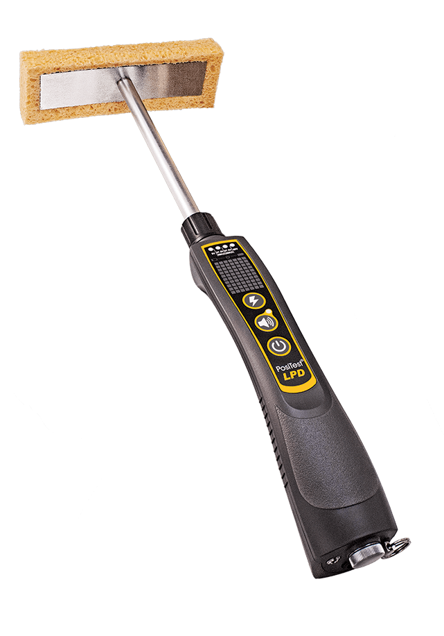
Low-voltage wet sponge detectors are used for thin coating systems, generally up to 20 mils (500 µm), subject to the applicable procedure. A moistened sponge is moved across the surface, allowing the solution to form a conductive path through a pinhole to the grounded substrate. While high-voltage holiday detector settings are typically based on coating thickness, low-voltage wet sponge detectors operate at prescribed test voltages and sensitivities specified by the applicable test method or procedure. The resistance threshold—typically 80 or 90 kΩ—largely determines whether the detector alarms.
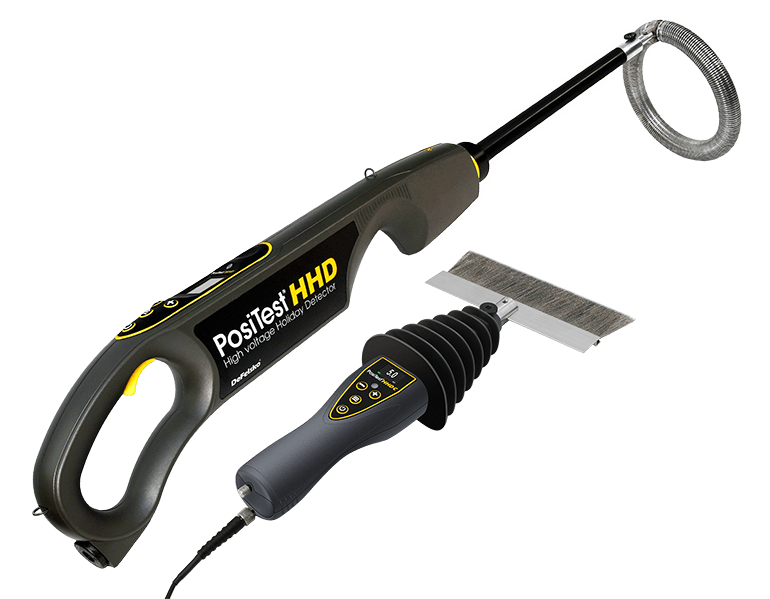
High-voltage holiday detectors are the instruments most commonly recommended for thicker protective coatings, such as those applied to pipelines and other infrastructure. Because these instruments do not use a conductive medium like water, they must apply enough voltage to overcome the insulating properties (dielectric strength) of air, a process called electrical breakdown. The thicker the coating layer, the greater the distance the current must travel, and the more voltage is required. For this reason, setting the correct voltage is a critical step when testing with a high-voltage detector.
High-voltage holiday detection relies on applying sufficient electrode voltage to reliably locate defects without damaging the coating itself. Achieving that balance depends in large part on selecting the correct test voltage. Problems can occur if the wrong voltage is used:
Despite the importance of selecting the correct voltage, the coating inspection industry has historically offered widely varying recommendations.
One of the most common approaches was the "100 volts per mil" rule of thumb: multiply coating thickness in mils by 100, which worked out to roughly 4 V/µm in metric units. This formula was easy to remember and quick to apply. Where rules of thumb were not used, inspectors relied on voltage tables published in industry standards.
Depending on which standard was referenced, however, the specific voltage recommendations varied widely and were sometimes inconsistent within the same standard. The chart below compares the volt/mil recommendations published in previous versions of several major standards.
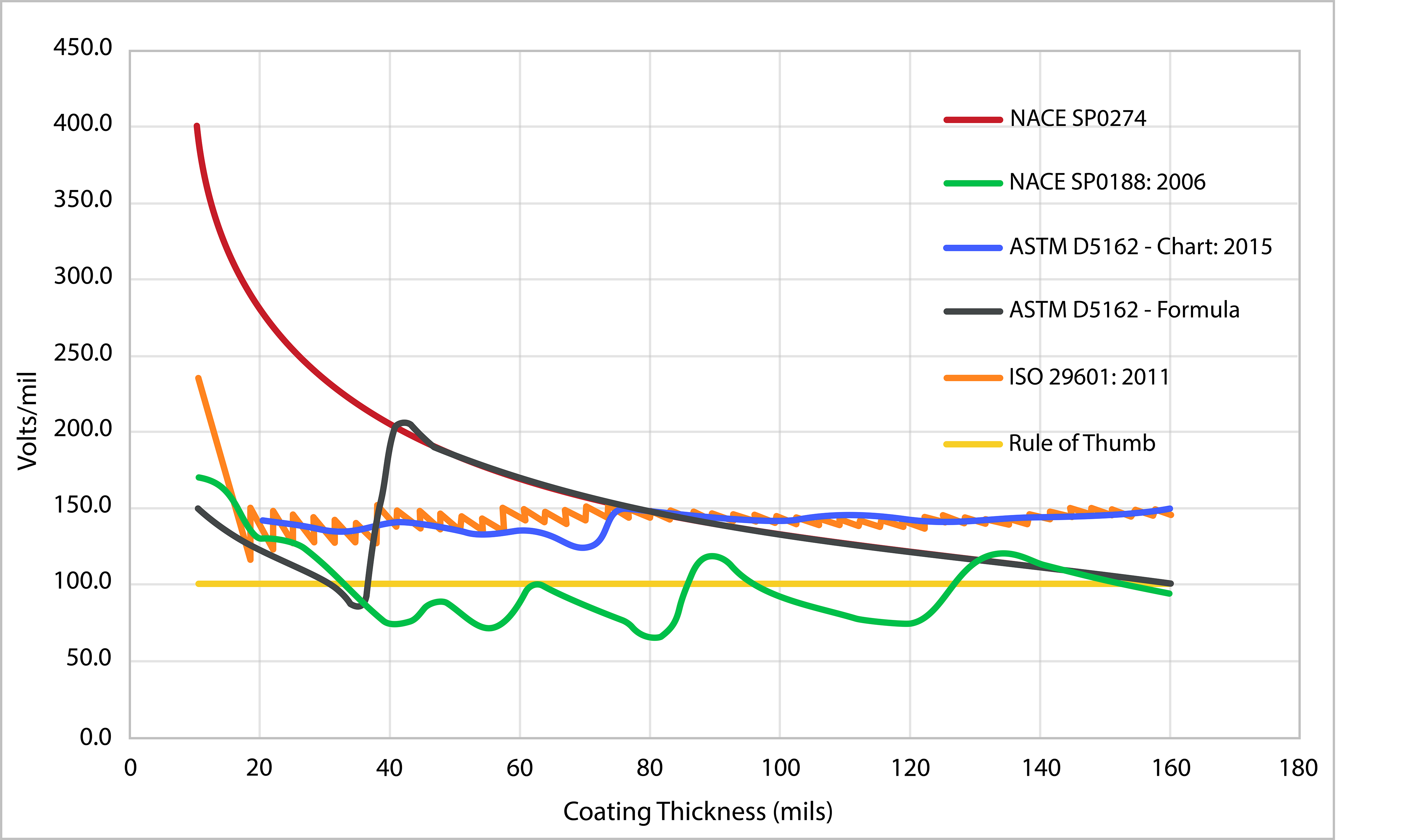
Beyond inconsistency, these recommendations were developed from historical practice and field experience rather than from a clearly defined scientific model.
Voltage recommendations were also shaped by concerns that high voltages could burn through the coating, which led specifiers to favor lower values. In practice, however, many common protective polymer coatings have dielectric strengths above 500 V/mil (about 20 V/µm), and some materials, such as fusion-bonded epoxies, exceed 1,000 V/mil (about 40 V/µm). These dielectric-strength values are substantially higher than the revised test voltages for many common, fully cured protective coatings. Accordingly, test voltages can often be increased considerably above older recommendations without approaching coating breakdown. The coating manufacturer's maximum permitted test voltage should still be confirmed.
The lack of consistency and scientific backing for older recommendations highlighted a clear need for experimental testing and a reevaluation of voltage selection.
Controlled laboratory testing found that voltages higher than those traditionally used are required to reliably detect holidays. A study by Walker et al. tested coated steel panels with known artificial holidays to determine the voltage needed to detect 100% of holidays.¹ The experimental data aligned with Paschen’s law, the physics-based relationship that describes the voltage required to create an electrical arc between two electrodes.
Under standard atmospheric conditions, the voltage required to achieve electrical breakdown in air is given by:²
Metric (microns): V = 170 + 2.48d + 58√d
Imperial (mils): V = 170 + 63d + 293√d
Where:
V = required voltage (volts)
d = gap distance (microns or mils)
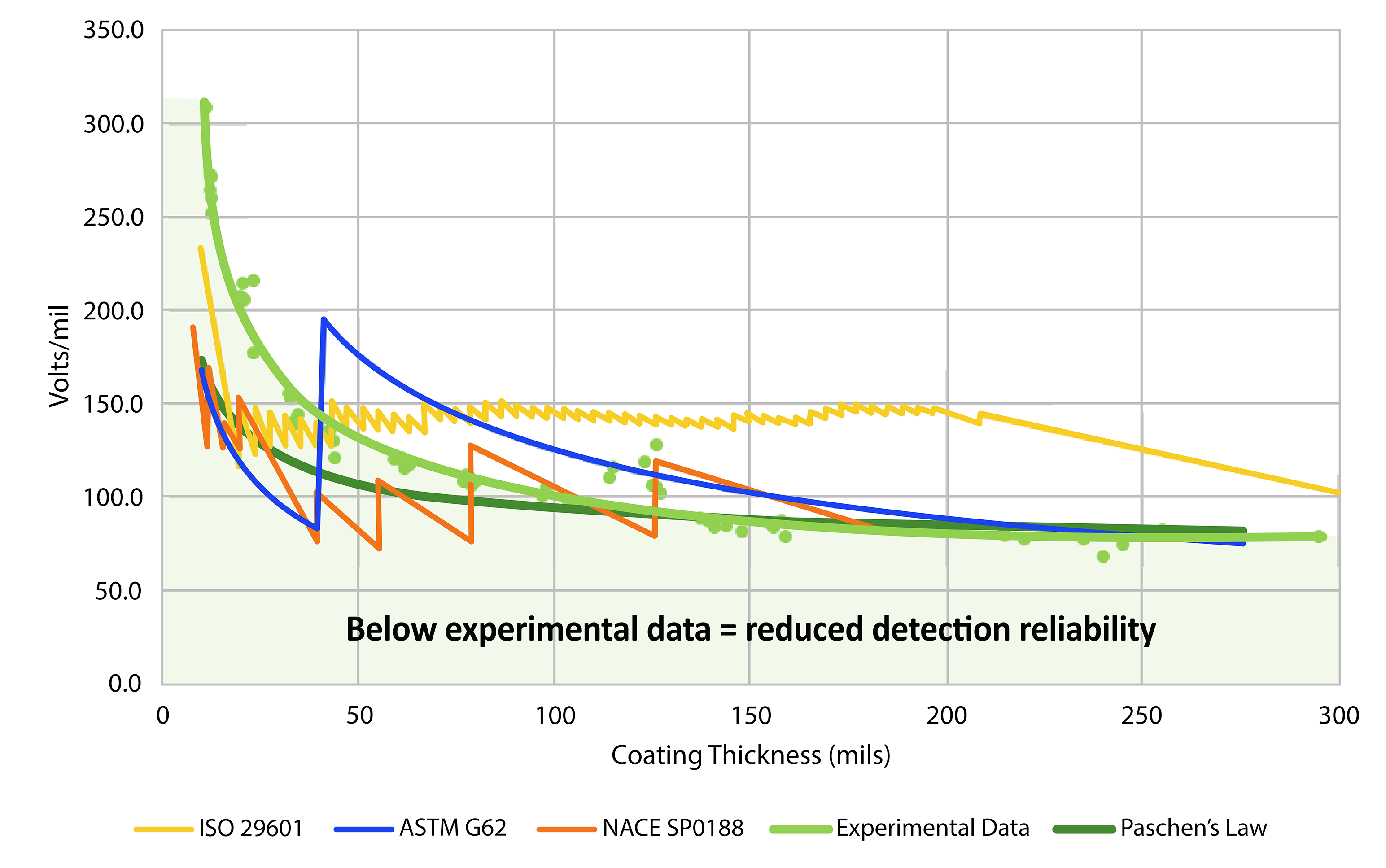
Differences between this equation and the experimental findings can be caused by real-world variables, such as debris on the electrode or coating, variations in coating thickness, small gaps between the electrode and coating, and changes in environmental conditions.
The combined experimental and theoretical data showed that many traditional recommendations were too low to reliably detect all holidays, particularly for coatings thinner than 50 mils (1,250 µm). At greater coating thicknesses, 100 V/mil comes closer to the theoretical air-breakdown threshold, but it remains below the current recommended test voltage because it contains no margin for field conditions. In light of these findings, an update to the formulas and recommendations was clearly warranted.
To account for real-world conditions and to better align the theoretical formula with experimental findings, field margins were applied to the theoretical minimum. The breakdown equation was multiplied by 1.5 and a baseline of 1,500 V was added, yielding:
Metric (microns): V = 1,500 + 1.5 × (170 + 2.48d + 58√d)
Imperial (mils): V = 1,500 + 1.5 × (170 + 63d + 293√d)
Where:
V = recommended test voltage (volts)
d = coating thickness (microns or mils)
1.5 = margin for surface roughness, debris, and electrode condition
+1,500 V = baseline to overcome small, inconsistent electrode-to-surface gaps in field conditions
This formula sets recommended voltages comfortably above the minimum determined in the Walker study while remaining below the dielectric strength of many common, fully cured protective coatings. Using these voltages will reduce the likelihood of missed holidays or damaging the coating system.
The table below illustrates the gap between the updated formula and several older approaches. The previous recommendations are shown for historical comparison only; they have been superseded in the current standards and should not be used in new specifications. Existing projects should follow the contractually invoked edition unless the parties approve use of the updated method.
The difference is most pronounced for thinner coatings, where prior recommendations fell significantly short of the voltage actually needed to reliably detect defects.
Worked Example: Putting the Formula to Use
For a 635 µm (25 mil) coating:
V = 1,500 + 1.5 × (170 + 2.48[635] + 58√635)
V = 1,500 + 1.5 × (170 + 1574.8 + 1461.5)
V ≈ 6,309 V
For a 1,000 µm (40 mil) coating, the same formula yields approximately 8,226 V.
In other words, the recommended test voltage for a coating thickness of 635 µm is approximately 6,300 V, not the 2,500 V suggested by the traditional 100 V/mil rule. For a coating thickness of 1,000 µm, the recommended test voltage is approximately 8,200 V, not the 4,000 V predicted by older linear rules.
The updated formula is scientifically backed and experimentally validated. It has been adopted in recent updates to several major industry standards. The updated method is grounded in Paschen’s law, supported by controlled testing, and incorporated into ASTM G62-23, NACE SP0188-2024, ASTM D5162-24, ASTM D4787-24, and ISO 29601:2026.
To test with confidence, inspectors should:
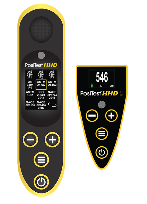
The PosiTest HHD and PosiTest HHD C include built-in voltage calculators for these standards, simplifying setup and reducing manual calculation errors.
On concrete, reliable testing also depends on establishing a conductive return path. Concrete moisture, embedded reinforcement, and conductive underlayments can significantly affect electrical continuity, so the concrete-specific procedure in ASTM D4787 should be followed and operation verified across representative areas.
The revised voltage settings are grounded in the physics of electrical breakdown in air and supported by controlled testing. When applied in accordance with the governing standard and the coating manufacturer’s limits, they improve detection reliability while minimizing the risk of coating damage.


